AVC-1 Slagleformer Parts Package - Wiring Guide
Introduction
There are just a few connections to wire up and you'll be enjoying your AVC-1 Slagleformer pre-amp. These are the wiring notes for the typical 6 input all RCA build. For wiring you can choose to use any wire flavor that you wish – after all it is your project! We typically ship these out with a length of OCC copper enamel coated solid core wire. Alternately we have OHNO stranded wire. The OHNO stranded wire is shown in these notes below.
Tools and supplies needed include wire cutters, wire strippers, small hex wrenches (for enclosure screws), soldering iron and fume extractor, solder. Always perform any soldering / tinning in a well ventilated space with a good solder fume fan/filter.
NOTE: When using OCC copper solid core wire you must tin the ends before making connections. This process involves burning off the enamel insulation using a hot soldering iron tip with a bit of solder applied. Do this in a VERY well ventilated space with a good solder fume fan/filter.
To start with remove the lid (6 hex screws) and also the 4 hex screws in each corner of the back panel.
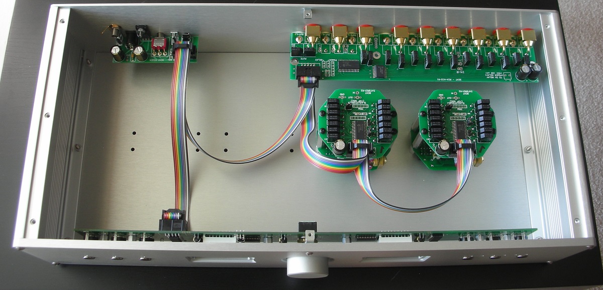
AVC-1 as it is shipped (after lid is removed)
Loosen the screw at the bottom / centre of the back panel allowing the back panel to tip back a bit. This makes it easier to get at the connections needed on the bottom pcb of the Slagleformer modules.
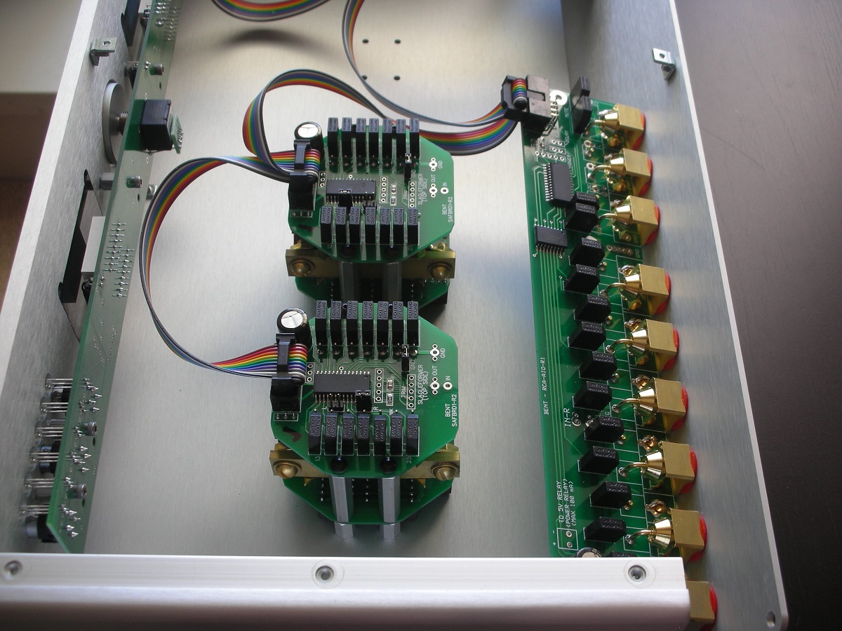
Back Panel tipped back for better Slagleformer access
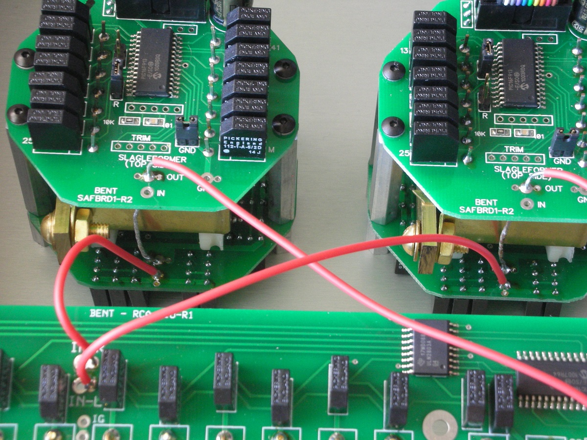
First we'll make the connection from the OUT pad on the TOP AND BOTTOM PCB on each Slaglefromer module to the back panel RCA jack PCB output jacks. This connection is right at the output rca jacks and is marked “R” and “L” for the right and left channels.
To make the connection at the Slagleformer module top and bottom pcb you may either install a short jumper from top to bottom, run separate wires for the top and bottom pcb connections to the back panel, or alternately you can strip back about 1-3/4” of the wire bare, tin it sparingly and insert it through the top pcb and down to the bottom pcb. Shown here is an example of the latter method.
Note that to keep the wire from shorting to the autoformer body you must either insert some heat shrink on the section between the pcbs or gently bend the tinned wire away from the module.
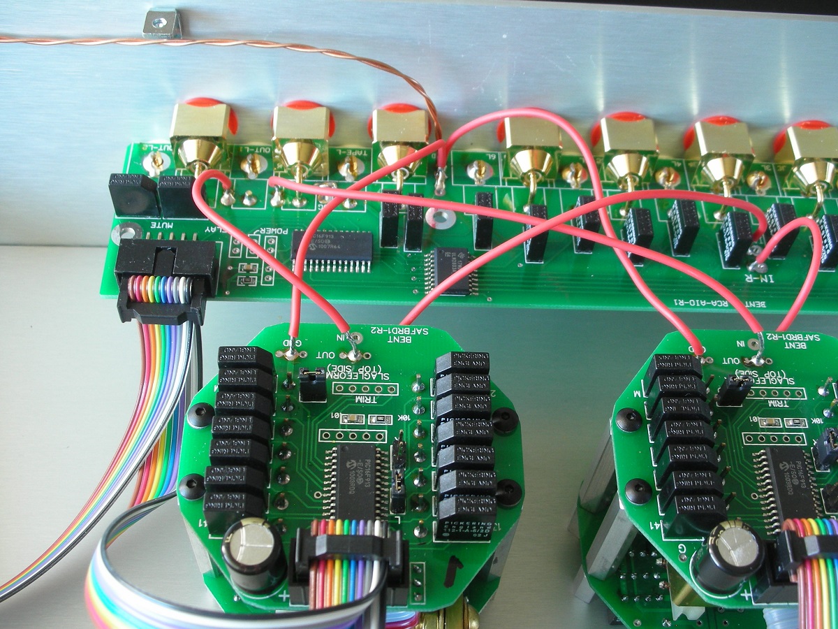
Route this wire over to the output pcb and make the connection at the “R” and “L” points for the left and right module respectively. These output wiring connections are shown here:
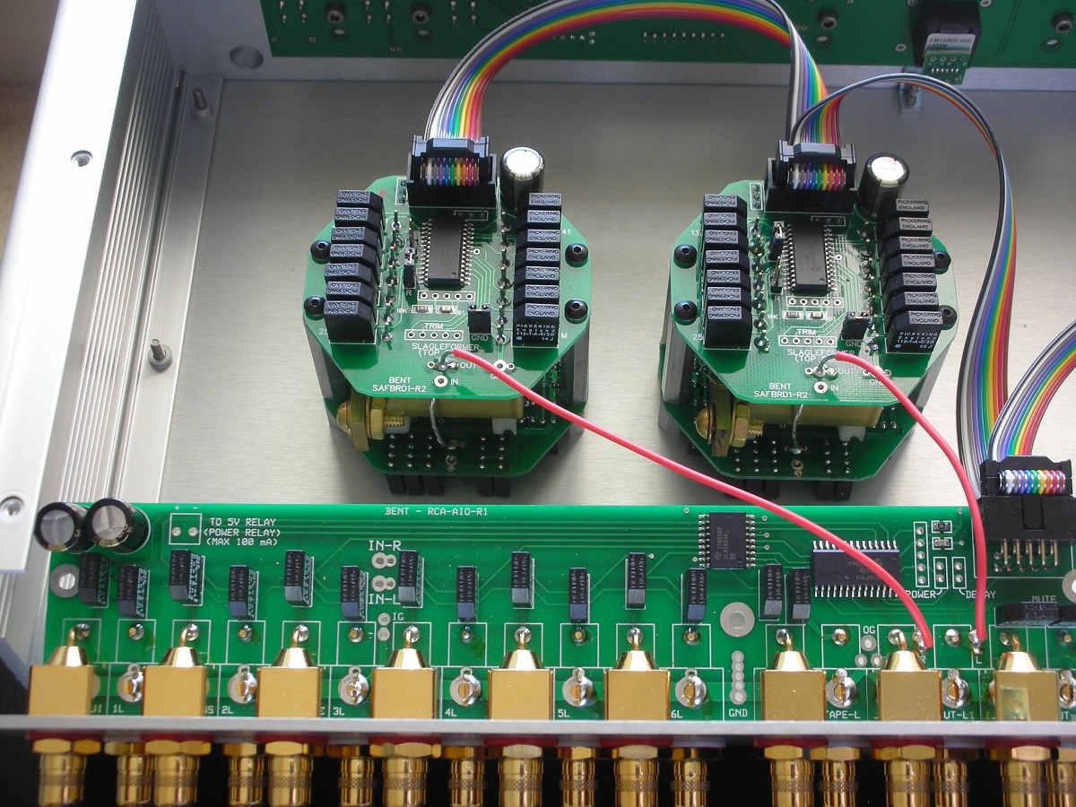
Slagleformer OUT connections (top and bottom pcb) to back panel pcb
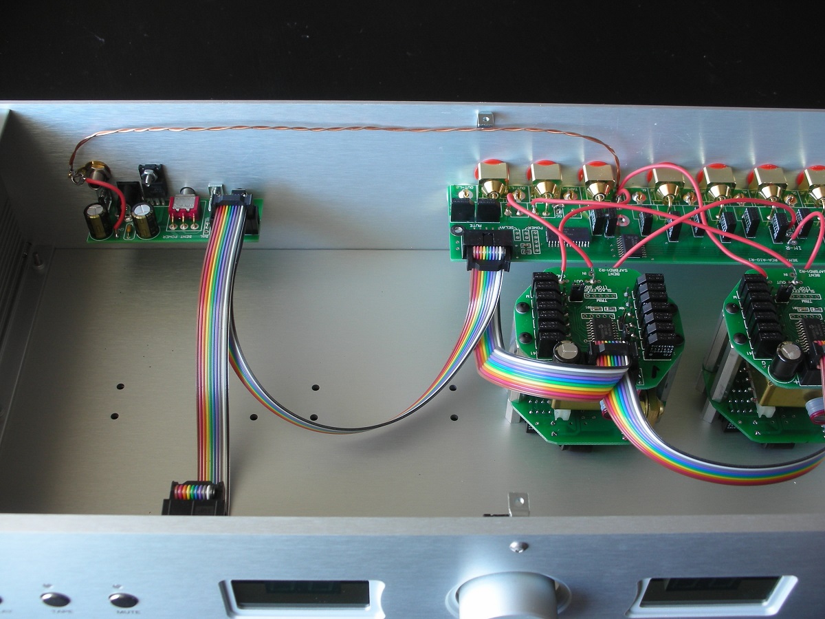
Next we'll connect the “IN” point on the BOTTOM PCB ONLY of each Slagleformer module to the “IN-L” and “IN-R” points on the back panel pcb. No connection is needed at the top PCB 'IN' position – although if using solid core wire you can choose to route the wire down through that top pcb to the bottom pcb. These connections are shown here:
Slagleformer IN connections (bottom pcb only) to back panel pcb
Now that the bottom pcb connections are complete snug up the screw at the bottom centre of the back panel and replace and tighten the 4 6-32 screws.
Finally we will make the required ground connections.
Slagleformer GND to back panel pcb. Make this connection with the same wire used for the signal path wiring preformed in the steps above. This connection goes from the GND connection point on each Slagleformer TOP PCB ONLY to one of the series of holes marked GND on the back panel pcb. Do not solder the back panel pcb GND point until the additional ground wire in the following step is installed.
Slagleformer Ground connection to Back Panel PCB
Next we run a wire from the GND point on the back panel pcb to the enclosure ground tab just above the power supply pcb. I use a couple lengths of OCC copper wire twisted together to make this connection all the time – even if the rest of the wiring is OHNO wire. Any wire 24AWG or bigger will work fine for this connection. Tin or strip back a longer length at the ground tab end and run it through the tab and form a loop for other ground connections. This is not an issue when using the back panel RCA pcb but other build configurations with more hardwiring sometimes involve more connections at that chassis ground point than the hole in that ground tab can accommodate.
Ground connection on Back Panel PCB to Chassis Ground
Now connect a short wire from the power supply pcb ground point to the ground tab just above it.
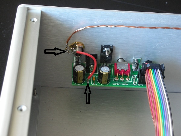
Power Supply Ground to Back Panel PCB to Chassis Ground
Now we install a very small jumper wire to connect the input grounds to the output grounds on the back panel PCB. This jumper is located next to the output RCA jacks and is shown here:
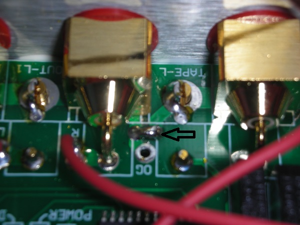
Input Ground to Output Ground Jumper on Back Panel PCB
Verify at this point that the R and L jumpers on the top pcb of each slagleformer module match the wiring – ie that the Left wired module has the L jumper installed and the right side wired module has the R jumper installed.
If the GND jumpers on each Slagleformer module are installed remove them now. This connection has been made via the wiring above and the jumpers are not needed.
That is it. Take a few minutes to carefully review the wiring before testing.
Final Testing
Each module in the AVC-1 parts pack is pre-assembled and tested prior to shipping. Every input and every Slagleformer step is confirmed working on an Audio Precision analyzer so likely you are ready to install and enjoy your new preamp. If you don't have a meter then just install the unit in your system and give it a go!
If you have a meter you can put it on an ohms setting and then place the probes from output hot to ground on the left side. Plug in the AVC-1 supply and run the volume up and down. You should see the meter read from a very low value (close to 0 ohms) down at mute and then rise up as you turn the volume up. Test the other channel in the same way. The exact values are not critical – just watch that the readings start down close to 0 and rise as the level is adjusted up. After that simple test simply install and enjoy.
As always please feel free to contact me anytime at johnc@bentaudio.com or call at (604) 560-2959 with any questions that come up during assembly.
AVC-1 Manual Download
Enjoy The Music Review of the new AVC-1 Slagleformer pre-amp project